Design Description
The framework consists of two sections, a reconstruction core library for developing new voxelizer or visualizer components and a windows based graphical user interface for loading implemented components and applying all the tasks, described in previous sections. Figure 1 shows the main components of the system and their relationships.
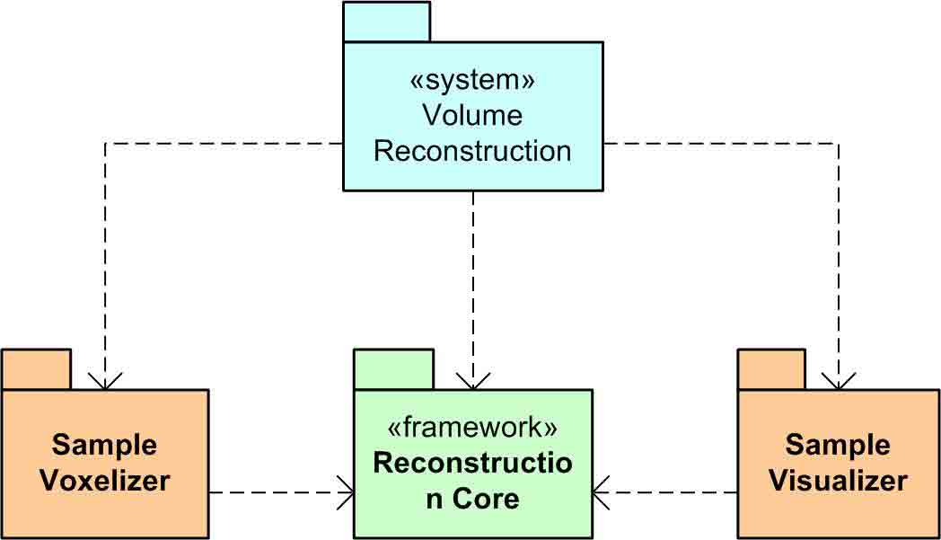
Figure 1: Main components and their relations
in the volumetric reconstruction system.
The connection between GUI and implemented components are easily made, at runtime, using the late binding technique. The using of different technologies such as multi-threading, have made our GUI as a user friendly tool for running, testing and comparing various approaches in volumetric reconstruction and presentation.
Architecture
The framework is designed using object oriented architecture as is shown in figure 2. Different classes have been declared in the reconstruction core library - shown with green color - for ease of development in other parts. Any new voxelizer and visualizer component, which are shown in orange, should be inherited from VoxelizerBase and VisualizerBase abstract classes respectively.
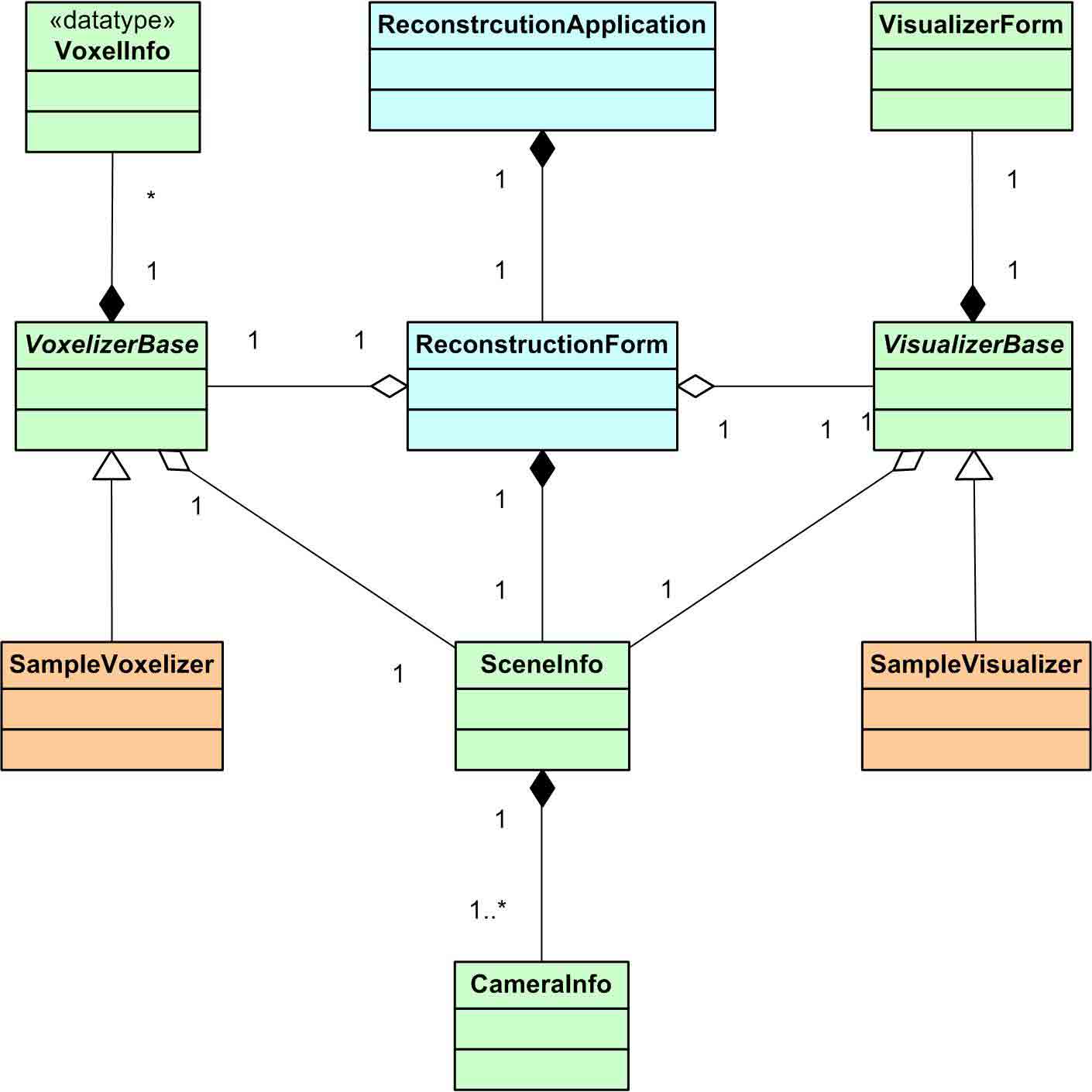
Figure 2: Class diagram of a complete reconstruction system.
The graphical user interface application module, consist of two main classes. The first is a Win32 application class which instantiate the second class. The second is a windows form inherited window, with many controls defined inside, doing all required operations.
Implementing Voxelizer
Voxelizers are components, which are used by the host application, for reconstructing the three dimensional scene in volumetric space. All the required information for reconstruction process, such as information about scene and the camera configuration, is stored in an abstract class from which all other voxelizer components should be inherited. Scientists and developers, who need to develop a new volumetric reconstruction algorithm, should start their work by creating a new class library project in visual studio. A reference to the reconstruction core library - binary of the framework - should be added to the project, at the next step. Then add reconstruction component, as a new class which inherits from VoxelizerBase class defined in the framework and override all required abstract members. In the constructor of your class call the base constructor, passing the name of your voxelizer component. The code of a sample volumetric reconstruction component is presented in the following part.
using ReconstructionCore;
{
public class
SampleVoxelizer :
VoxelizerBase
{
public SampleVoxelizer() :
base("Sample
Voxelizer")
{
// construct the component
}
protected
override bool InitializeData(SceneInfo sceneInfo)
{
// here you should initialize the component
return true;
}
protected
override bool ResetData()
{
// here the state of voxelizer should be
restored
// to its first configuration and any previous
// data shouild be ignored
return true;
}
protected
override bool UpdateData(Bitmap[] images)
{
// do the reconstruction and update the voxels
in
// this method
return true;
}
protected
override bool UnInitializeData()
{
// uninitialize all stored resources in this section
return true;
}
}
}
The VoxelizerBase abstract class is the root of all voxelizer components. It store voxels information in Voxels property which can be set using SetVoxel and SetVoxels methods. The projection of voxel on the image plane of each camera can be computed using GetImage method. There are some helper methods for computing statistical information which should be called appropriately by developers. ConsistencyChecked should be called after each consistency checking and SearchSpace should be called for each traversed voxel during the reconstruction process. Also for informing users about the current progress state AdvanceProgress should be called, with a parameter ranged from 0 to 100.
Implementing Visualizer
After the reconstruction process using voxelizers the framework use visualize components for presenting output. There is an abstract base class also for inheriting visualizers from. Required information such as scene information, reconstructed voxels and a reference to a visualizer window is stored and managed in this base class named VisualizeBase.
using ReconstructionCore;
namespace SampleVisualizer
{
public class
SampleVisualizer :
VisualizerBase
{
public SampleVisualizer() :
base("Sample
Visualizer", true,
true)
{
// construct the visualizer
}
protected
override bool InitializeData(SceneInfo sceneInfo)
{
// here you should initialize the component
return true;
}
protected
override bool UpdateData(Color[, ,] voxels)
{
// update the model from given scene but do not
show
// the result on the screen
return true;
}
protected
override ToolStripItem[] GetCommands()
{
// return set of tool strip if any item which
will be
// shown when user right clicks on the visualizer window
return null;
}
protected
override void Refresh(bool forced)
{
// draw the model on the screen
}
protected
override bool Save(string file)
{
// save current image to the file with the
given path
return true;
}
protected
override bool UnInitializeData()
{
// uninitialize all stored resources in this section
return true;
}
}
}
To implement new visualizer components, add a new project and a reference to the framework as before. Then create a class and inherit it form VisualizerBase. Call the base constructor providing the visualizer name and values about using Direct3D and mouse navigation. The visualizer window can help you if it knows about your requirements. Finally override abstract members to present data as you want. The above sample code shows visualizer class which uses Direct3D and mouse navigation. A reference to output window and Direct3D device - in the case of presence - are stored in the VisualizerBase. Also a reference to the camera information, which should be used in the updating process, is stored. Background color also is one of the member data in the visualizer classes and should be used in the updating process.
Scene Information
Both voxelizer and visualizer components require to use information about scene including bounding area for reconstruction volume, per axis voxel resolution, number of cameras and information about each of them. The SceneInfo class stores all this information. SceneInfo class contains a typed list for storing cameras information.
Camera Information
We define the placement of each camera in the world by its eye position - optical center -, look at point, normalized up vector, field of view for Y axis (FOV), aspect ratio - width vs. height of image plane - and at last near and far distances. With this peace of information a camera's placement in the world space can be recognized as well as its view and projection matrices. There is a complete list of the cameras inside the scene which is stored in the SceneInfo class. The Camera Info class store all described information about camera plus some helpful member functions for navigating and replacing camera in the 3D space. PanViewport can be used to move the eye position and target parallel to the camera image plane. ArcViewport rotates eye position around look at point and MoveViewport moves eye position toward or away from look at point.